-
JRT Gear Units & Gearmotors
-
JRH Industrial Gear Units
-
JRP Planetary Gear Units
-
JRW Worm Gear Units
-
JD Three Phase Asynchronous Motors
-
JC Intelligent Drive Solutions
- JRTW Hybrid Right Angle Gearmotors
- JRKM, JRKB Hypoid Gear Units
- JRESR Stainless Steel Helical Gearmotos
- JRES Stainless Steel Worm Gearmotors
- JRSS Screw Lifters
- JRTM Spiral Bevel Right Angle Units
- JRGC Transfer Case
- JTA Shaft Mounted Gear Units
- JEC Escalator Units
- JN Agricultural Machinery Gear Units
- JGT Electric Rollers
English
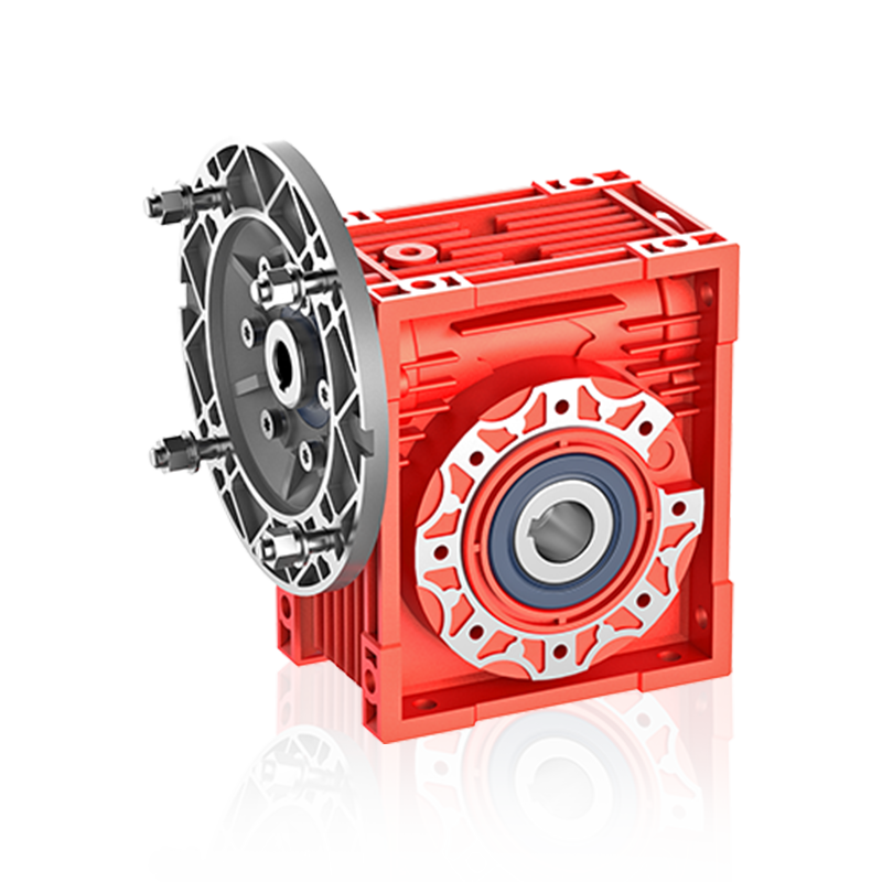
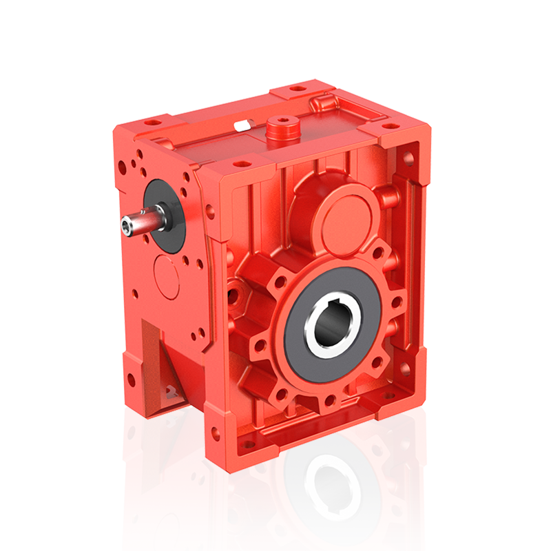
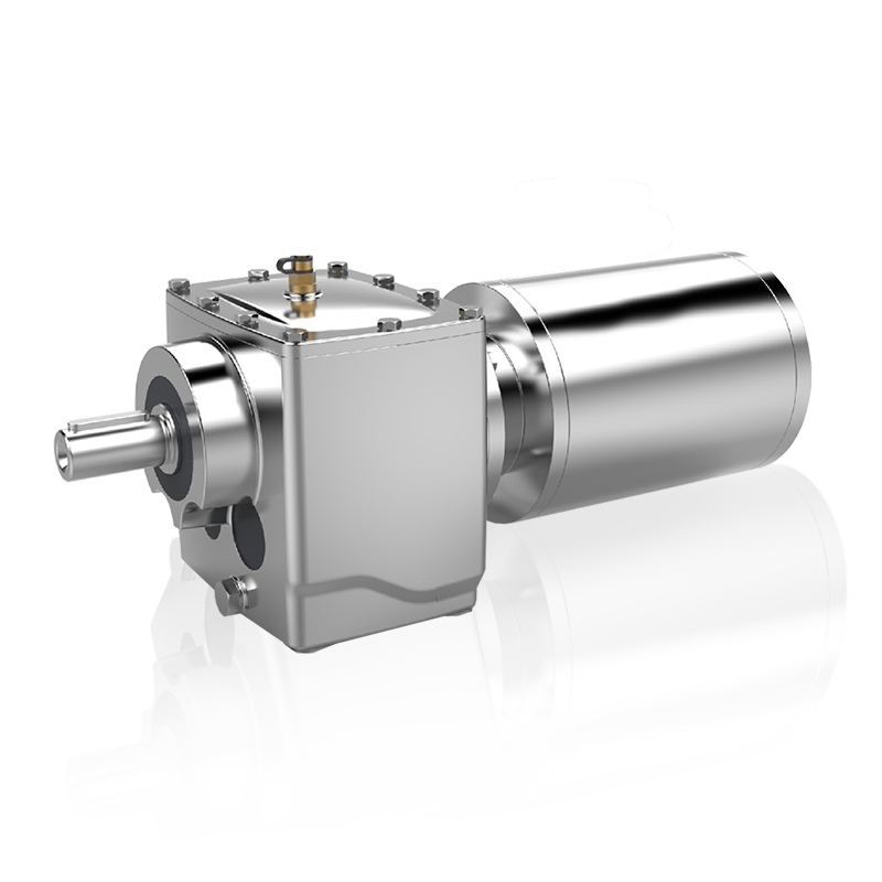
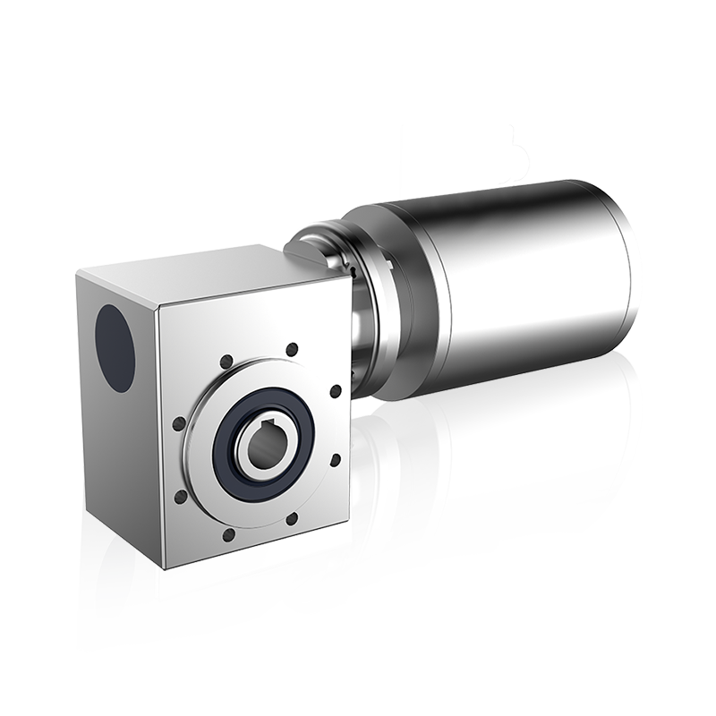
JRW Worm Gear Units
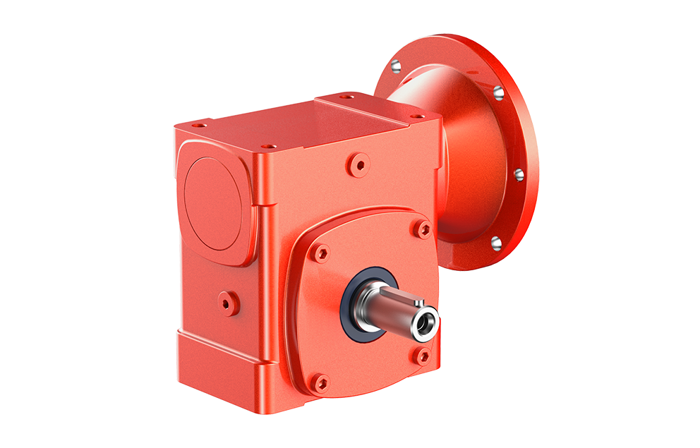
JRW300 Worm Gear Units
Product Highlight
| Size: | 310~360 |
| Ratio: | 5~100 |
| Input power: | 0.08~26.13HP |
| Output torque: | 113~11219 lb-in |
Ordering Information:
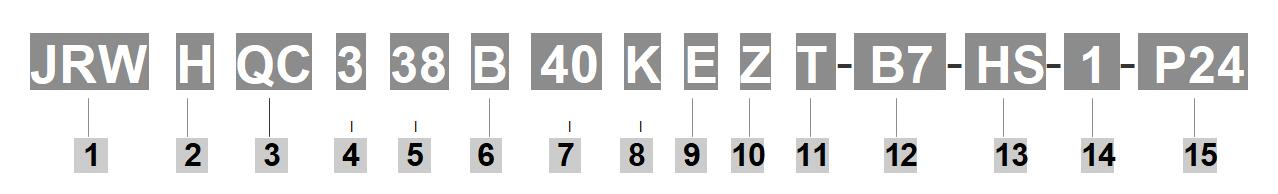
| 1 | Brand Code | JIE Worm Gear Reducer | 2 | Output Shaft Style | Blank – Solid Output Shaft H – JIE Hollow Output (setscrews both sides, bore size selectable) S – Hollow Output (setscrews one side, bore size fixed) |
|||||||||||||||||||||||||||||
| 3 | Input Shaft Style | Blank – Solid Projecting Input Shaft F - Quill Style Motor Flange RF – Coupling Style Motor Flange QC – Quick Connect Motor Flange (close coupled) |
4 | 3 – 300 Series | ||||||||||||||||||||||||||||||
| 5 | Center Distance(inches) | 10 – 1.00、13 – 1.33、15 – 1.54、18 – 1.75 21 – 2.06 、24 – 2.38 、26 – 2.62、30 – 3.00 32 – 3.25、38 – 3.75、52 – 5.13、60 – 6.00 |
6 | Base/Mounting Attachment * | Blank – No Base A – Horizontal base – Top Mount B – Horizontal base – Bottom Mount BRB – Riser Block – Top Mount C – Vertical High base – Right Mount D – Vertical Low base – Right Mount E – Vertical High base – Left Mount F – Vertical Low base – Left Mount R – JIE Bracket – Right Mount L – JIE Bracket – Left Mount M –Conveyor Flange Adptr – Right Mount N – Conveyor Flange Adptr – Left Mount V – Hollow Output Flange – Right Mount W – Hollow Output Flange – Left Mount X – Vertical Base – Rear Mount Y – Vertical Base – Front Mount *Projection of Base/Flange/Bracket assumes one is always looking into the input shaft in the #1 mounting position. |
|||||||||||||||||||||||||||||
| 7 | Exact Gear Ratio | Ratio to 1 5、7、7.5、10、12、15、20 25、30、40、50、60、80、100 Or Consult Factory for Availability |
8 | Lubrication | Blank – No lubrication K – Klubersynth UH1 6-460 S – Mobil SHC 634 X – Mobil 600W |
|||||||||||||||||||||||||||||
| 9 | Endcap or Fan | (332-360 only) E – Endcap (standard) F – Fan |
10 | Vent | Blank – Standard Vent Z - Pressure Vent (5 psi) |
|||||||||||||||||||||||||||||
| 11 | Oil Seal | Blank – Standard Seal T – Two Standard Input Seals |
12 | NEMA Motor Mounting |
|
|||||||||||||||||||||||||||||
| 13 | Output Shaft | (When facing Input and worm on top) G - Carbon Steel Output Projection – Left H - Carbon Steel Double Output Projection J - Carbon Steel Output Projection – Right |
14 | Mounting Positions | Blank - No Lubrication Supplied For Factory Prelubrication Indicate Mounting Position 1 – Standard Mounting (Worm over) 2-6 – Refer to Mounting Positions |
|||||||||||||||||||||||||||||
| 15 | JIE Output Bore Code | For H Series Only Specified in 1/16" increments. Example: 1 1/4” = P20 5/8 – P10、3/4 – P12、7/8 – P14、15/16 – P15、1 – P16、1-1/16 – P17、1-1/8 –P18、1-3/16 – P19、1-1/4 – P20 1-5/16 – P21、1-3/8 – P22、1-7/16 – P23、1-1/2 – P24、1-5/8 – P26、1-11/16 – P27、1-3/4 – P28、1-7/8 – P30 1-15/16 – P31、2 – P32、2-1/8 – P34、2-3/16 – P35、2-1/4 – P36、2-7/16 – P39、3-7/16 – P55 Note: 1. If you need motor, please note“with motor”and the model, power &poles of the motor. 2. Accessories are unassembled. You may assemble them according to your need. 3. Connect JIE for availability by center distance |
Copyright © JIE USA Inc. All Rights Reserved.